Pneumatics & Accessories
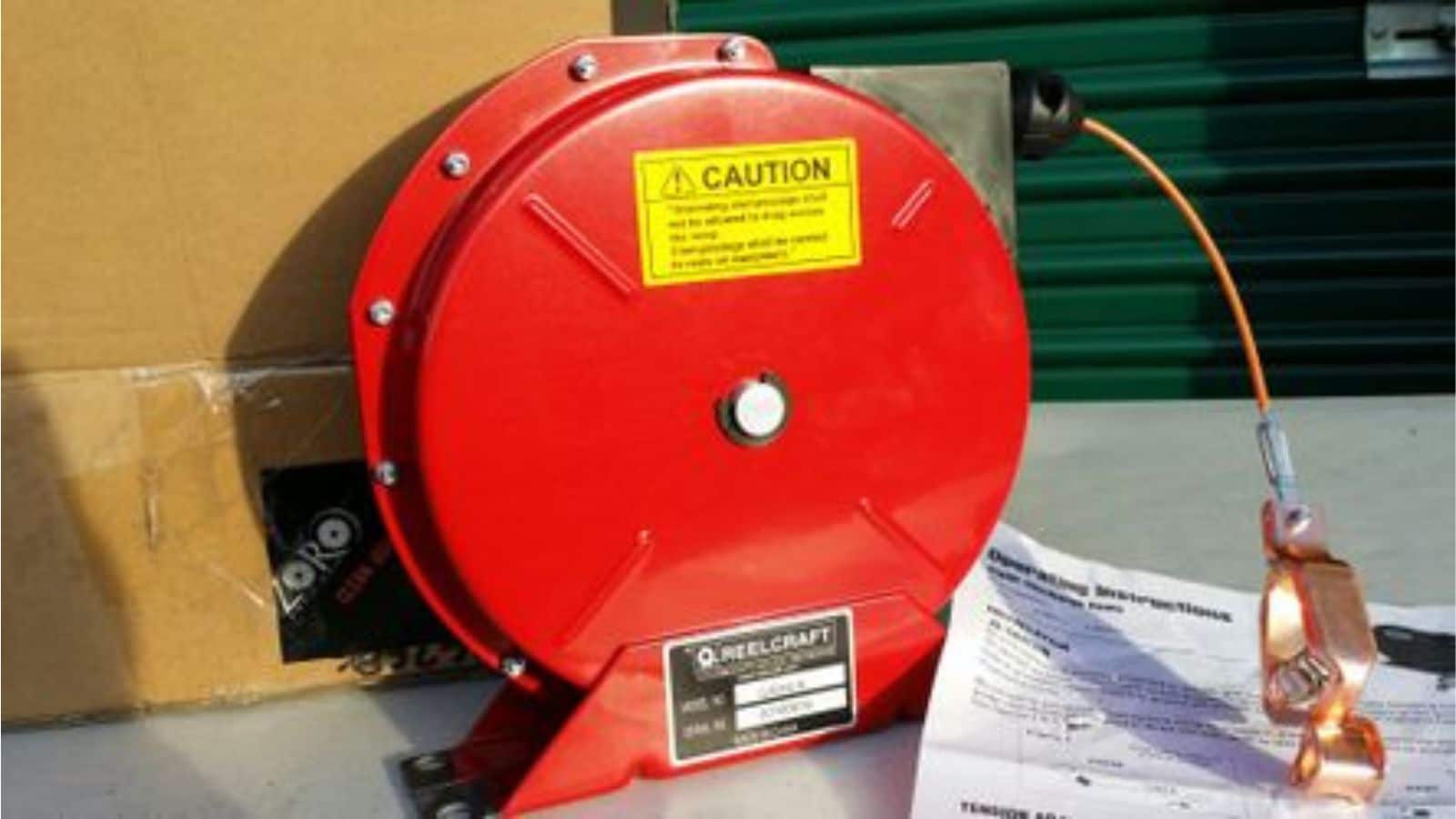
The Ultimate Guide to Spring Retractable Grounding Reels
The Ultimate Guide to Spring Retractable Grounding Reels: In industries where flammable vapors, gases, or...
+966 59 204 1946
No products in the cart.
Pneumatic systems are the silent workhorses behind countless industrial operations, from manufacturing and automation to process control. Yet, despite their ubiquity, many businesses grapple with inefficiencies, unexpected downtime, and escalating energy costs directly attributable to sub-optimal pneumatic infrastructure. At Aska Solution, we’ve witnessed firsthand the profound impact that a well-engineered, leak-free pneumatic system can have on operational performance and profitability. Our goal is not just to provide components, but to partner with you in creating an optimized, resilient system that truly drives your business forward.
This comprehensive guide is your blueprint to understand, design, implement, and maintain a pneumatic system that not only meets but exceeds industry standards for efficiency, reliability, and safety. We’ll delve into the foundational principles, data-driven component selection, and advanced strategies that ensure your system runs smoothly, minimizing waste and maximizing output.
pneumatic actuator performance.pneumatic system design and network topology reduce pressure drops and enhance overall compressed air system optimization.leak detection pneumatic techniques and sealing strategies can drastically reduce energy waste and improve system reliability.industrial air quality through proper filtration and drying extends component life and prevents costly system failures.air compressor efficiency and employing demand-side management are key strategies for substantial energy savings pneumatic systems.pneumatic safety standards and implementing rigorous protocols protects personnel and assets, ensuring compliant operations.Before you can truly optimize or build pneumatic system infrastructure, a deep understanding of its core principles is essential. This foundational knowledge allows us to move beyond reactive fixes to proactive design, ensuring every component works in harmony. In our experience managing complex industrial installations, this initial analytical phase is where the most significant long-term efficiencies are secured.
A pneumatic system is a carefully orchestrated network of devices, each playing a critical role. Understanding how these components – compressors, FRL units, valves, actuators, and tubing – interact is paramount. The compressor, for instance, is the heart, supplying the compressed air. The FRL (Filter-Regulator-Lubricator) unit conditions this air, ensuring it’s clean, at the correct pressure, and properly lubricated for downstream components. Valves control the direction and flow of air, while actuators convert pneumatic energy into mechanical motion. Finally, the tubing and fittings serve as the arteries and veins, delivering air throughout the system.
The interdependencies are complex. An undersized FRL unit, for example, can restrict flow, leading to inadequate pressure for an actuator, reducing its pneumatic actuator performance. Conversely, a valve with a slow response time can introduce delays in a high-speed application, impacting productivity. We often advise clients that neglecting these interdependencies during pneumatic system design is a common pitfall, leading to unforeseen bottlenecks and reduced system longevity. Properly understanding the FRL unit function is a critical first step in preventing many downstream issues.
Air flow dynamics are the physics of how compressed air moves through your system. This involves understanding pressure, volume, and velocity. Pressure is the driving force, while flow rate (volume per unit time) dictates how much work can be done. When we assess a system, we meticulously quantify the air flow requirements for each application. This isn’t just about ensuring there’s ‘enough’ air; it’s about ensuring the right amount of air at the right pressure at the right time.
For instance, a rapid-cycling cylinder demands high instantaneous flow, while a gripping application might require consistent, lower pressure. Calculating the cumulative air consumption, considering both continuous and intermittent demands, allows us to accurately size compressors and air receivers. We utilize sophisticated calculations to predict pressure drops across various components and pipe lengths, which is crucial for maintaining consistent pressure at the point of use. Over-pressurizing a system to compensate for poor flow dynamics is a major source of wasted energy and one of the first areas we examine for energy savings pneumatic systems.
The initial investment in accurately sizing a pneumatic system might seem significant, but the long-term economic benefits are undeniable. An undersized system leads to chronic pressure fluctuations, reduced tool performance, increased cycle times, and premature component wear. This translates directly into higher maintenance costs, lower productivity, and increased energy consumption as compressors work harder and longer to compensate.
Conversely, an oversized system results in higher capital expenditure than necessary and often leads to the compressor operating in inefficient load/unload cycles. We’ve consistently seen that choosing the right industrial components and sizing them correctly from the outset can lead to an average of 15-30% reduction in energy costs over the system’s lifespan. For many of our enterprise clients, we’ve demonstrated that this economic case is compelling enough to prioritize precision in the initial pneumatic system design, ensuring every element from the compressor to the smallest fitting contributes to overall compressed air system optimization.
Effective pneumatic component selection is not a guesswork game; it’s a meticulous process guided by data and application-specific requirements. Relying on intuition or outdated specifications can lead to recurring problems, suboptimal pneumatic actuator performance, and increased operational costs. At Aska Solution, we advocate for a data-driven approach, ensuring every part of your system is precisely matched to its intended function.
Actuators are the muscles of your pneumatic system, converting compressed air into linear or rotary motion. Selecting the correct actuator requires a detailed analysis of the load it will move, the speed required, the cycle frequency, and the environmental conditions. We meticulously gather data on:
We then cross-reference this data with manufacturer performance curves, which detail an actuator’s force output at various pressures, its theoretical cycle times, and its expected lifespan under specific conditions. A common technical issue we help businesses fix is the selection of an actuator based solely on its diameter, without considering the dynamic load and required speed. This often results in sluggish performance or premature failure. By precisely matching load data to these curves, we ensure optimal pneumatic actuator performance and longevity.
Valves control the flow, direction, and pressure of air within your system. Their selection hinges on three critical factors: function, flow capacity (Cv value), and response time.
We once worked with a client who struggled with slow robotic arm movements. Our analysis revealed that their control valves had insufficient Cv values and slow response times for the rapid cycles required. By upgrading their system architecture and selecting valves based on detailed flow rate analysis, they saw a 20% improvement in operational efficiency and cycle speed.
The FRL unit function is vital for maintaining industrial air quality and protecting downstream components. Each part of the FRL (Filter-Regulator-Lubricator) has specific data points crucial for selection:
Ignoring these specifications can lead to contaminated air reaching sensitive components, causing premature wear, corrosion, and operational failures. We emphasize that proper FRL unit function is a non-negotiable aspect of robust pneumatic system design.
The integrity and efficiency of your entire pneumatic system heavily rely on appropriate air piping materials and fittings. This often overlooked area is critical for maintaining pressure, preventing leaks, and ensuring system longevity.
air compressor efficiency and contributing to higher energy savings pneumatic systems potential if corrected.We ensure that all air piping materials and fittings meet or exceed the maximum operating pressure and temperature, preventing blowouts and leaks that compromise system performance and safety.
A truly optimized pneumatic system is a product of strategic pneumatic system design. It’s about more than just connecting components; it’s about creating an intelligent, efficient, and reliable network. Our approach at Aska Solution focuses on long-term performance and minimizing operational disruptions.
The layout of your compressed air supply significantly impacts efficiency and maintenance.
Pros: Easier maintenance for a single unit, potentially better air compressor efficiency due to fewer, larger compressors.
Cons: Extensive piping network can lead to greater pressure drop over distance, higher initial installation cost for long runs, and a single point of failure.
Pros: Reduced pressure drop, localized control, redundancy if one compressor fails, can be tailored to specific area needs (e.g., dedicated oil-free compressor for cleanroom).
Cons: Higher maintenance complexity across multiple units, potentially lower individual air compressor efficiency for smaller units, higher initial capital cost for multiple compressors.
We perform a thorough analysis, considering facility size, demand distribution, future expansion plans, and critical applications to recommend the optimal network topology. For large facilities with varying demands, a hybrid approach often provides the best balance of efficiency and reliability, contributing to overall compressed air system optimization.
Pressure drop is the bane of pneumatic efficiency. Every PSI lost due to friction or restriction translates into wasted energy and reduced performance at the point of use. Our pneumatic system design actively seeks to minimize this.
Loop Systems: Creating a ring main around the facility ensures air can reach any point from two directions, improving pressure stability and availability.
Minimize Bends & Fittings: Every bend, elbow, or connector introduces resistance. We design layouts that use the fewest necessary fittings and gentle curves rather than sharp angles.
Proper Slope & Drain Points: For lines carrying moist air, we ensure a slight slope (1-2 degrees per 10 feet) with strategically placed drain points to prevent condensate accumulation, which can cause corrosion and slugging.
By rigorously optimizing pipe sizing and layout, we can substantially improve energy savings pneumatic systems and ensure consistent pressure, which is critical for consistent pneumatic actuator performance.
For mission-critical operations, unplanned downtime due to pneumatic system failure is unacceptable. Redundancy planning is about building in safeguards to ensure continuous operation.
We calculate the financial impact of downtime versus the cost of implementing redundancy measures to provide an informed recommendation. For a manufacturing plant operating 24/7, the ROI on redundancy planning, which improves uptime and reliability factors, is often realized very quickly by preventing production losses. This proactive approach is a cornerstone of our compressed air system optimization philosophy.
Leaks are the silent energy thieves of any pneumatic system, often accounting for 20-30% of total compressed air consumption, and sometimes even more in older systems. At Aska Solution, we treat leak prevention not as a periodic check, but as a continuous, quantitative strategy for maintaining system integrity and realizing significant energy savings pneumatic systems.
One of the most effective methods for leak detection pneumatic systems use is ultrasonic technology. Compressed air escaping a leak generates high-frequency turbulent flow, creating ultrasonic sound waves that are inaudible to the human ear. Ultrasonic detectors convert these sounds into an audible frequency, allowing technicians to pinpoint even the smallest leaks.
leak detection pneumatic services within months.For a client in the automotive industry, our leak detection pneumatic audit uncovered numerous small leaks across their assembly lines, collectively costing them over $25,000 annually in wasted energy. Repairing these leaks not only saved them money but also improved the consistency of their tools and pneumatic actuator performance.
Pressure decay testing is a quantitative method to assess the overall integrity of a section or an entire pneumatic system. It involves isolating a section of the system, pressurizing it to a specific level, and then monitoring the pressure drop over a defined period (e.g., 30 minutes to an hour).
leak detection pneumatic efforts more precisely.This method helps us track the effectiveness of ongoing compressed air system optimization efforts and ensures we continue to build pneumatic system infrastructure that is truly leak-free.
Prevention is always better than cure. Proactive sealing strategies involve selecting the right materials and applying best practices during installation to minimize the likelihood of future leaks.
air piping materials that offer superior sealing properties.By combining rigorous leak detection pneumatic with proactive sealing strategies, we ensure that the systems we design and optimize achieve and maintain peak performance, contributing immensely to energy savings pneumatic systems.
The quality of compressed air is often overlooked until system failures or product contamination occur. Poor industrial air quality can lead to costly component damage, reduced operational efficiency, and even product spoilage. Aska Solution prioritizes robust air quality management as a core pillar of compressed air system optimization.
Compressed air contains various contaminants originating from the ambient air, the compressor itself, and the piping system. These include:
We conduct thorough contaminant analysis, which typically involves:
Understanding these contaminant levels allows us to prescribe the correct filtration and drying equipment, protecting your investment and ensuring the longevity of components. When our team tackles this issue on-site, they often find that simple, inexpensive monitoring tools can identify significant issues before they escalate.
To standardize industrial air quality, the International Organization for Standardization developed ISO 8573-1. This standard classifies compressed air quality based on three main criteria: particulates, water, and total oil content. Each criterion is assigned a class number (e.g., Class 1.2.1), indicating the maximum allowable levels.
We work with you to define the required ISO 8573-1 class for each application within your facility. Based on this, we specify the appropriate multi-stage filtration system, which might include:
1. General Purpose Filter: Removes large particulates and bulk liquid.
2. Coalescing Filter: Removes oil aerosols and smaller particulates.
3. Adsorption Filter (Activated Carbon): Removes oil vapors and odors.
This precise application of ISO 8573-1 standards ensures that your pneumatic system design integrates the necessary safeguards for product quality and component protection.
Water vapor is a major threat to pneumatic systems, causing corrosion, freezing in lines, and washing away lubricants. Dryer technologies are essential for managing this, and we compare their efficiency and maintenance data to recommend the best fit:
Pros: Low operating cost, simple maintenance.
Cons: Not suitable for freezing environments or very dry air requirements.
Pros: Very dry air, critical for sensitive applications or outdoor piping in cold climates.
Cons: Higher operating costs (purge air or heated regeneration), more complex maintenance.
Pros: No electricity, no moving parts, quiet.
Cons: Higher cost per CFM, requires purge air, limited dew point.
We analyze your specific dew point requirements, energy consumption goals, and maintenance capabilities to select the most suitable dryer technology, ensuring your industrial air quality is consistently high and your energy savings pneumatic systems potential is maximized.
“Many businesses view compressed air as a utility, but rarely consider its quality. Ignoring proper filtration and drying is akin to pouring dirty, watery fuel into a high-performance engine; it will inevitably lead to costly breakdowns and reduced lifespan.” – Dr. Eleanor Vance, Industrial Engineering Consultant
Even the best pneumatic system design and pneumatic component selection can be undermined by poor installation. At Aska Solution, we understand that meticulous installation practices are crucial for the long-term reliability, safety, and efficiency of your system. Our methodologies ensure that every build pneumatic system project is executed to the highest standards.
A significant percentage of system leaks and component failures can be traced back to improperly made connections. We enforce rigorous standards for secure connections:
air piping materials.We train our technicians extensively in these best practices because a single loose connection can compromise the entire leak detection pneumatic strategy and lead to significant energy savings pneumatic systems losses.
Proper routing and support of pneumatic tubing and piping are essential for preventing mechanical stress, abrasion, and potential leaks.
air piping materials like metal. This prevents sagging, reduces vibration, and protects connections. Over time, unsupported lines can lead to fatigue failures.Our project managers perform detailed stress analysis during the pneumatic system design phase to anticipate potential issues and incorporate preventive measures into the installation plan, ensuring longevity and consistent pneumatic actuator performance.
After installation, we conduct thorough post-installation audits to verify that the system performs as designed and meets all specified parameters. This is a critical step in our build pneumatic system methodology.
leak detection pneumatic scan using ultrasonic equipment is performed to ensure the system is truly leak-free from day one.pneumatic actuator performance under load.These audits not only validate our work but also provide you with crucial benchmark data for future performance monitoring & predictive maintenance strategies. It’s how we ensure compressed air system optimization from the moment your system goes live.
In the modern industrial landscape, reactive maintenance is a costly relic. At Aska Solution, we empower our clients with advanced performance monitoring & predictive maintenance strategies to ensure maximum uptime, efficiency, and longevity of their pneumatic systems. This proactive approach minimizes unexpected failures and optimizes resource allocation.
The integration of Supervisory Control and Data Acquisition (SCADA) systems and the Internet of Things (IoT) has revolutionized how we manage pneumatic infrastructure. These technologies provide real-time visibility into every aspect of your system.
Compressor discharge pressure and temperature
System pressure at various points of use
Air flow rates (CFM/LPM)
Dew point after dryers
Filter differential pressure
Energy consumption (kW)
This real-time data acquisition is foundational for effective compressed air system optimization and allows us to continually refine the way you build pneumatic system operations.
Raw data is just numbers; trend analysis turns that data into actionable intelligence. By continuously logging and analyzing performance metrics over time, we can identify subtle degradations that precede major failures.
air compressor efficiency, often due to wear, cooling issues, or leak detection pneumatic needs.industrial air quality.pneumatic actuator performance might suggest worn seals, reduced pressure, or valve issues.Identifying these trends allows us to intervene before a catastrophic failure occurs, transforming reactive repairs into scheduled, manageable maintenance tasks.
Based on the insights gained from trend analysis, we develop predictive maintenance schedules. This moves beyond time-based or reactive maintenance to a condition-based approach, optimizing the timing of repairs and replacements.
energy savings pneumatic systems against the cost of monitoring systems.For many of our clients, implementing these performance monitoring & predictive maintenance strategies has resulted in a double-digit percentage reduction in maintenance costs and a significant boost in operational uptime, proving the tangible value of intelligent system management.
Compressed air is one of the most expensive utilities in manufacturing. Roughly 7-10 HP of electrical energy is needed to produce 1 HP of compressed air. Therefore, focusing on energy efficiency & cost reduction strategies within your pneumatic system offers one of the quickest and most significant returns on investment. At Aska Solution, we specialize in identifying and implementing solutions that dramatically lower your energy bills.
The compressor is the largest energy consumer in your pneumatic system. Its control strategy profoundly impacts air compressor efficiency.
Pros: Highly efficient in fluctuating demand environments, as they only produce the air needed, consuming significantly less energy.
Cons: Higher initial capital cost.
We conduct detailed air audits to analyze your demand profile. For many facilities with fluctuating or partial load demands, upgrading to a VSD compressor can deliver energy savings pneumatic systems of 25-50%, often providing a payback period of just 1-3 years. Combining custom fabrication with structural engineering solutions, we often integrate VSD compressors into existing complex systems with minimal disruption.
While compressor efficiency is critical, managing the demand side of your system – where the compressed air is actually used – often uncovers even greater energy savings pneumatic systems potential.
leak detection pneumatic program is paramount. Fixing leaks is the lowest hanging fruit for energy savings.pneumatic system design.Our comprehensive audits help you build pneumatic system operations that are inherently lean, eliminating waste at every turn and drastically improving overall compressed air system optimization.
Compressors generate a significant amount of heat as a byproduct of compression – often 80-90% of the electrical energy input is converted to heat. This heat is usually vented to the atmosphere, representing a colossal waste of energy. Heat recovery systems capture this waste heat and put it to productive use.
Water Heating: Pre-heating boiler feedwater, washdown water, or domestic hot water.
Space Heating: Heating factory or office spaces.
Process Heating: Specific industrial processes that require warm air or water.
energy savings pneumatic systems achievable.For many industrial facilities, particularly those with high hot water or space heating demands, installing a compressor heat recovery system can reduce heating costs by 5-10%, translating into substantial annual savings and a rapid ROI. This truly showcases how we build pneumatic system solutions that are not only efficient but also environmentally responsible.
Safety in pneumatic systems is non-negotiable. High-pressure air, rapidly moving components, and potential for sudden releases pose significant hazards. At Aska Solution, our pneumatic system design and operational guidelines are meticulously crafted to adhere to the strictest pneumatic safety standards and regulatory compliance, ensuring the protection of your personnel and assets.
Safety valves and pressure relief devices are critical components of any pneumatic system, designed to prevent catastrophic over-pressurization.
pneumatic safety standards and manufacturer guidelines. This verification is crucial, as a stuck or improperly set relief valve can have severe consequences.Failing to correctly size or maintain these devices puts an entire facility at risk.
Lockout/Tagout (LOTO) procedures are fundamental for protecting workers during maintenance, service, or repair of machinery and equipment where the unexpected startup or release of stored energy could cause injury. Pneumatic systems inherently store significant energy.
Shutting off the air supply: At the main compressor and individual isolation points.
Draining residual pressure: All stored air must be safely vented.
Locking and Tagging: Applying physical locks and tags to valves and energy isolation devices to prevent accidental re-energization.
Verifying Zero Energy: Confirming that all energy sources, including pneumatic, are completely dissipated before work begins.
Adherence to LOTO procedures is a cornerstone of pneumatic safety standards and a legal requirement in many jurisdictions. We emphasize that there are no shortcuts when it comes to worker safety.
Operating a compliant pneumatic system requires adherence to a multitude of local, national, and international pneumatic safety standards and regulations.
pneumatic system design principles, safety requirements for pneumatic fluid power systems, and noise levels.We provide guidance on navigating these complex regulatory landscapes, ensuring that your build pneumatic system infrastructure not only performs efficiently but also meets all necessary compliance requirements. Our expertise helps you avoid penalties, maintain insurance validity, and, most importantly, create a safe working environment.
Even the most meticulously designed and maintained pneumatic systems can encounter issues. When problems arise, a systematic, data-driven troubleshooting common issues approach is far more effective than trial and error. At Aska Solution, we provide a diagnostic framework to quickly identify root causes and implement lasting solutions.
The first step in effective troubleshooting common issues is to accurately identify the specific performance anomaly. This involves more than just noticing a problem; it’s about defining it precisely.
This systematic approach, rather than jumping to conclusions, ensures that we gather all relevant data before proceeding, enhancing compressed air system optimization efforts.
Once an anomaly is identified, root cause analysis is employed to uncover why the problem occurred, rather than just treating the symptoms. This often involves working backward from the symptom using gathered data.
Symptom: Pneumatic actuator performance is weak.
Potential Causes: Insufficient pressure at the actuator, internal leak in the actuator, clogged exhaust port, undersized valve, air supply issue, regulator malfunction.
Data to Check: Pressure at actuator inlet, valve Cv rating, system pressure upstream, regulator setting.
Symptom: Compressor turns on and off too frequently.
Potential Causes: High system demand (e.g., new machinery), large system leaks, small air receiver, faulty pressure switch, air compressor efficiency decline.
Data to Check: Leak detection pneumatic scan results, actual air demand vs. compressor output, receiver volume, pressure switch calibration.
Symptom: Condensate at points of use, corrosion.
Potential Causes: Dryer malfunction, bypass of dryer, high humidity environment, insufficient drain frequency.
* Data to Check: Dryer dew point, drain trap functionality, ambient humidity.
By systematically evaluating the data against known pneumatic system design principles, we can accurately pinpoint the root cause and implement a lasting solution.
Every problem, once resolved, presents an opportunity to implement preventive measures and strengthen your pneumatic system design.
root cause analysis, and the corrective action taken. This creates a valuable knowledge base for future troubleshooting common issues.leak detection pneumatic findings are always at older push-to-connect fittings in a high-vibration area, upgrading to compression fittings might be a preventive measure.performance monitoring & predictive maintenance strategies accordingly.pneumatic safety standards and best practices.Learning from every failure is how Aska Solution helps you continuously build pneumatic system resilience and move towards truly proactive, compressed air system optimization.
Optimizing your pneumatic system is not merely a technical exercise; it’s a strategic investment in your operational efficiency, safety, and bottom line. From the fundamental principles of pneumatic system design to advanced performance monitoring & predictive maintenance strategies, every element plays a crucial role in achieving a leak-free, high-performing infrastructure. We’ve seen how meticulously addressing industrial air quality, prioritizing leak detection pneumatic efforts, and embracing energy savings pneumatic systems can transform operational costs and enhance productivity.
At Aska Solution, we are more than just providers; we are your partners in navigating the complexities of industrial pneumatics. Our expertise in pneumatic component selection, air compressor efficiency, and adherence to pneumatic safety standards ensures that your system is not just functional, but truly optimized for peak performance and longevity. We are committed to helping you build pneumatic system solutions that are robust, efficient, and future-proof.
leak detection pneumatic checks?A1: For most industrial facilities, we recommend performing comprehensive leak detection pneumatic surveys using ultrasonic equipment at least once a year. For critical systems or those with high energy consumption, quarterly or bi-annual checks may be beneficial. Between formal surveys, operators should be trained to listen for obvious leaks.
air compressor efficiency?A2: Improving air compressor efficiency directly translates into significant energy cost reductions, as the compressor is typically the largest energy consumer in a pneumatic system. Other benefits include reduced wear and tear on the compressor, leading to lower maintenance costs, and a smaller carbon footprint for your operation.
pneumatic actuator performance?A3: The most common causes of poor pneumatic actuator performance include insufficient pressure or flow at the actuator (often due to undersized air piping materials or valves), worn seals within the actuator, incorrect pneumatic component selection for the application’s load, or contamination in the air supply affecting internal mechanisms.
industrial air quality so important, and how is it measured?A4: Industrial air quality is crucial because contaminants (water, oil, particulates) cause corrosion, wear, and malfunction of pneumatic components, leading to increased maintenance and downtime. It also protects end products from contamination. Air quality is typically measured against ISO 8573-1 standards, which classify air based on particulate count, water dew point, and total oil content.
energy savings pneumatic systems just by addressing leaks?A5: Absolutely. Leaks are often the biggest source of wasted energy in pneumatic systems, accounting for 20-30% or more of compressed air costs in many facilities. Fixing these leaks can provide immediate and substantial energy savings pneumatic systems, often with a very rapid return on investment.
FRL unit function components, and why are they necessary?A6: FRL stands for Filter-Regulator-Lubricator.
They are necessary to condition the compressed air, ensuring it’s clean, at the correct pressure, and sometimes lubricated, protecting downstream equipment and optimizing pneumatic actuator performance.
pneumatic safety standards I should be aware of?A7: Key pneumatic safety standards include OSHA regulations (e.g., Lockout/Tagout procedures, safe use of tools), ISO standards (e.g., ISO 4414 for general rules relating to fluid power systems, and ISO 8573-1 for air quality), and local building/electrical codes. These standards cover everything from safe pneumatic system design and installation to operation and maintenance.
Don’t forget to share it
Related Articles
The Ultimate Guide to Spring Retractable Grounding Reels

How White Numbered RFID Cards Enhance Identification and Security

Complete Guide to ACT 3 FIG.602/1002/1502 Hammer Union Lip Seal for Sour Service USA
Boost Efficiency: Top Pneumatic Accessories for Industry
Maximize Your Machines: Boost Pneumatic Filtration Lifespan
Cut Costs: 7 Ways Proactive Pneumatic Maintenance Pays Off